transmissions and shafts 368
Engine alignment, like so many other onboard mechanical details, falls squarely into the category of Out of Sight, Out of Mind. If the engine and shaft are set properly the first time, alignment rarely needs to be revisited. Regrettably, that’s a very big “if.” In my experience as a marine mechanic and boatyard manager, I’d estimate that well over half of the boats that I see-new and used alike-suffer from some degree of misalignment.
Undesirable vibrations, premature cutless-bearing wear, transmission-bearing failure, and shaft breakage can all result from poor alignment. For a quick check, see if your propeller and shaft require excessive effort to turn while the vessel is in the water. (Note that all final alignments are completed when the vessel is afloat.) If they do, you need to investigate further.
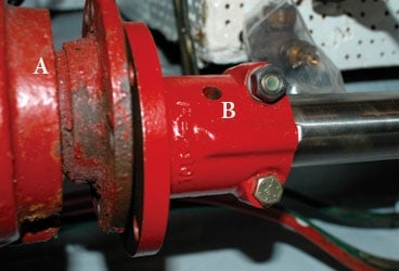
Begin by looking at the alignment between the transmission’s output coupling and the propeller shaft’s coupling; you’ll find that it’s easier to adjust the transmission and the engine than the shaft. The faces of these couplings must be not only centered relative to each other but also parallel. Before you take any tools to the couplings, you must first calculate the free hanging weight of the shaft and its coupling, then counter it by lifting the shaft with the appropriate amount of force. For instance, a 3/4-inch-diameter shaft weighs 1.5 pounds per foot, while a 1 1/4-inch shaft weighs 4.2 pounds per foot. For more detailed information on obtaining weight calculations, consult the Western Branch Metals website (www.wbmetals.com); under eBrochures & Data Sheets, click on Aqualoy 22 Rudder Brochure.
Determining the weight of the coupling is a bit trickier. You could remove and weigh yours; you could also contact a coupling manufacturer, such as Buck Algonquin Marine Hardware (www.buckalgonquin.com), to obtain the weight of an equivalent model. Once you’ve calculated the weight of the shaft and coupling, counter that weight by applying half the amount in an upward force, using a fish scale or other hanging scale as a measurement device. Say the shaft has a hanging weight of 7 pounds; you’d want to put 3.5 pounds of upward pressure on it. This will counter any sag in the shaft that could cause problems.
After you’ve removed the coupling bolts and separated the two couplings, spray the faces of the bolts and couplings with a light lubricant, such as CRC Formula 6-56 Marine Lubricant. This will aid in rotating them during the alignment procedure.
First, ensure that the couplings are centered. (The pilot and pilot receiver-a protrusion and indentation near the center of the respective couplings-should engage each other.) Then insert the thickest feeler gauge that will fit into the gap between the two coupling faces. A maximum of approximately 0.001 inch of misalignment is considered acceptable for every inch of coupling-face diameter. Thus, a 5-inch diameter coupling should accept a feeler gauge that’s no larger than 0.005 inch (less is better) at any point around the interface.
If the gap is larger at any point, the engine’s motor mounts will have to be adjusted. When you view the couplings from aft facing forward, if an excessive gap existed at the 3-o’clock position, then the front of the engine would have to be moved to starboard. If a gap existed at the 6-o’clock position, the front of the engine would have to be lowered. Once the gap size is acceptable, rotate the shaft coupling 180 degrees and recheck the measurements. If any change has occurred, then the coupling, the shaft, or the fit between the two isn’t true; in such a case, they’ll then need to be removed and taken to a shaft shop for inspection, fitting, and facing.
Steve D’Antonio, a regular Cruising World contributor, offers services for vessel owners, boatbuilders, and others in the marine industry through Steve D’Antonio Marine Consulting. Next month, he writes about bilge-pump maintenance.

