grounds 368
The question of whether to bond various pieces of metal gear and underwater metals in a circuit or leave them isolated is a subject that’s sure to generate heated debate among dockside sages. If the argument could be made for one approach or the other without regard to other related grounding issues, then isolation would surely win out. However, other grounding considerations-including electrocution prevention, the mitigation of damage from lightning strikes, and the need to provide a safe path to ground for short circuits in the AC and DC electrical systems-argue in favor of an overall grounding system. Moreover, if done properly, this system helps to minimize stray current corrosion that can affect any node on the circuit.
To make an already complex topic simpler, let’s limit the scope to fiberglass boats and leave boats with metal hulls for another occasion.
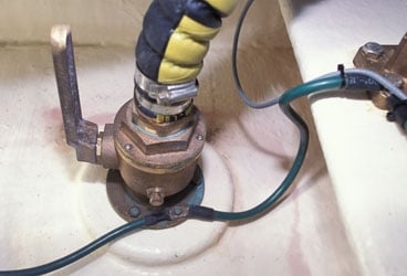
The bonding of various metals, such as the stainless steel of rudderstocks, the bronze of seacocks and through-hull fittings, the Aquamet alloy of propeller shafts, and the aluminum of tanks and spars, may seem like an invitation for corrosion. Every effort typically is made to keep dissimilar metals apart, especially those that are far apart from each other on the galvanic scale, such as aluminum and copper alloys.
The key difference with a comprehensive bonding system is that all of these dissimilar metals are part of a circuit that also includes a sacrificial anode, typically made of zinc. Because zinc is especially galvanically ignoble, when it’s connected to the DC bonding system, it affords galvanic protection to all other metals above it on the galvanic scale. How this is all accomplished on your boat, however, requires a bit of detailed elaboration.
The American Boat & Yacht Council, which writes standards for how boats should be built and maintained, recommends that all non-current-carrying metal equipment, particularly gear in the engine room or gear that comes in contact with fuel lines or bilge water, be interconnected via a properly sized grounding wire.
Paraphrasing A.B.Y.C. guidelines, the grounding conductor that’s attached to each device must be no smaller than one size under that which is required for current-carrying conductors supplying the device and must not be less than 16-gauge wire.
This means, for example, that if you install an inverter that relies on a 1/0 DC supply cable, it must be bonded using a cable that’s no smaller than a 1-gauge wire; yes, this means that both the supply and the grounding cables will be roughly 1/2 inch in diameter. The reason for this is that if the DC cabling short-circuits against the inverter case, there must be a safe path to ground for fault current and that path must utilize a cable that’s as large or nearly as large as the cable supplying the current.
Many vessels utilize a copper-strip bonding bus that’s routed fore and aft, and to which devices requiring bonding are attached. The strip is typically connected to a hull-mounted anode, a DC negative bus or battery terminal, and the engine block. If used, this bus strip must be at least 1/32-inch thick and not less than 1/2-inch wide. Connections made to this strip must be made by a machine screw that is threaded into a hole tapped in the strip that will receive at least three full threads; otherwise, they must be through-bolted. Self-tapping screws shouldn’t be used.
Finally, linking the DC bonding system with the AC safety ground and the lightning-grounding systems means that most metal masses on board are part of the grounding system. And to protect all the elements of this boat-wide circuit, diligent attention should be paid to the sacrificial zincs that will prevent galvanic corrosion. Frequent inspection and replacement of the zincs is a small price to pay in exchange for protection against potentially harmful or life-threatening shorts from any of the electrical sources on a boat.
Steve D’Antonio offers services for boat owners, builders, and the marine industry through Steve D’Antonio Marine Consulting (www.stevedmarineconsulting.com).


