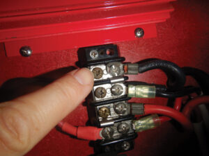
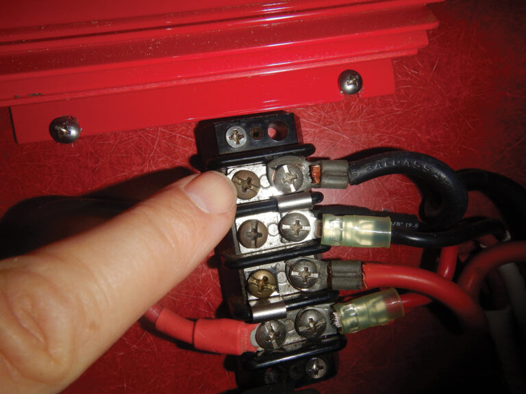
Imagine hand cranking your engine, or retrieving your anchor using a manual windlass, or lighting kerosene navigation lamps every night. While you might curse it from time to time, your vessel’s electrical system makes cruising far more enjoyable, leisurely and safe. In my experience, failures are nearly always avoidable, and thus failure prevention must be proactive; the best approach is to go looking for trouble before it manifests itself, and there’s no time better than at the start of the sailing season.
Batteries
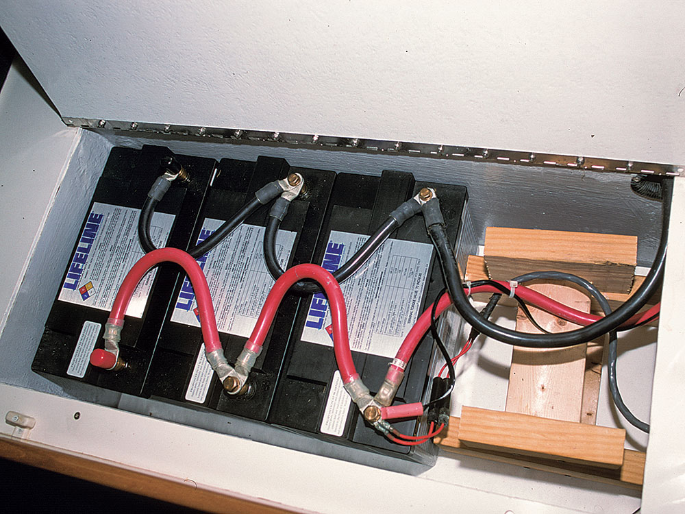
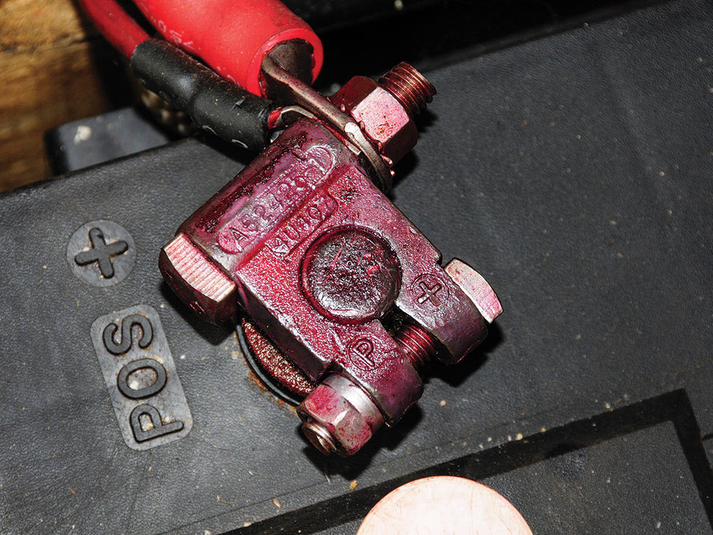
As providers of power for engine starting as well as navigation and communication gear, lights, fans, pumps and other systems, your vessel’s batteries are perhaps the most important part of the electrical system. Making certain they are reliable and well cared for should be a top priority. Begin by inspecting terminals; these should be tight, and free of all corrosion. To prevent the latter, my preference is for a conductive paste, such as T&B Kopr-Shield, on the contact surfaces (it is not designed to be slathered over completed connections), which are then coated with CRC Battery Terminal Protector.
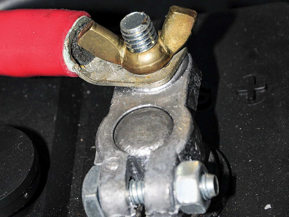
Ideally, batteries should be equipped with flag terminals, vertical lead or copper plates, through which a bolt is passed to secure cable ring terminals. Under no circumstances should wing nuts be used to secure ring terminals to batteries; always use a hex nut and bolt, preferably stainless steel or bronze. Batteries relying on automotive-style round posts must utilize an adapter lug or terminal. These are available in a variety of styles; however, those that rely on a through-bolt, rather than a cast-in-place stud, should be used. In order to keep resistance at a minimum, no more than four ring terminals should be placed on any single stud, and ideally, less. If any one of your batteries’ terminals supports more than four ring terminals, consider installing a bus bar to which some can be moved.
Because they convey especially high current, and since they are typically not equipped with overcurrent protection (i.e., a fuse or circuit breaker), battery cables used for starting purposes must be routed and protected with special care. As a result of the energy stored in the battery, and the diameter of the cable, a short circuit will spell almost certain disaster because the heat generation will quickly ignite nearby timber, fiberglass, insulation and so forth. The positive cable leading from the battery, or battery switch, to the engine starter, must be routed out of harm’s way, where it will not be repeatedly stepped on, or have gear stored on or dragged over it. Other than its connection to the starter, it must not touch the engine, transmission or motor mounts in any way, and it should be sheathed.
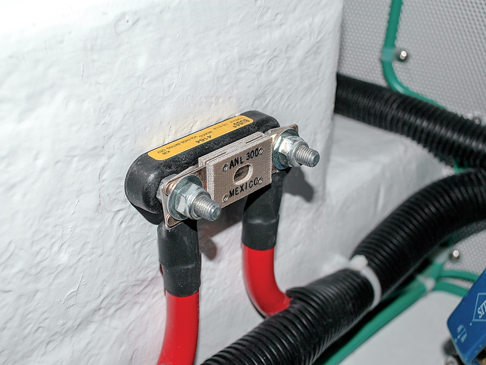
Unless contained in a box, positive battery terminals, as well as those on the starter post, must be fully insulated or enclosed. An ill-fitting rubber boot or cap is not sufficient; if any part of the terminal or stud is exposed then additional insulation must be installed. Starter cable runs and exposed terminals present a very real short-circuit danger; don’t dismiss these guidelines as unnecessary or overkill. On the subject of overcurrent protection, with the exception of starter circuits, a fuse or circuit breaker must be installed within 7 inches of every positive battery terminal. The distance between the battery terminal and the fuse or circuit breaker may be extended to 72 inches, provided the wire is supplementally sheathed within a conduit or ABYC-compliant loom.
Batteries themselves must also be securely mounted, ensuring they remain in place even in tumultuous sea conditions, or in the event of a knockdown or capsize. Most strap arrangements, unless they rely on a heavy-duty stainless-steel ratcheting buckle, are inadequate. Straps or buckles are simply too wimpy, the strap eyes are flimsy or the screws that secure them are too short (or worse, too short and made from mild steel). The most reliable battery supports rely on the aforementioned ratcheting strap, which passes under a robust battery shelf, or a tie rod with a strong back-clamp arrangement. While ABYC standards allow for up to 1 inch of battery movement in compliant installations, my preference is for complete immobilization.
Running Lights
Running lights, which are exposed to rain, spray and harsh UV rays, live a hard life. It’s no wonder I encounter so many that are either damaged or not working properly. In addition to ensuring they illuminate, you should inspect yours regularly to make certain the lenses are not cracked, crazed or faded.
For incandescent lights, plan on opening them at least seasonally to make certain they are free of corrosion and water accumulation. While conductive paste is well-suited to most electrical connections, because the positive and negative contact surfaces are very close together in most light bulbs, it should not be used in this application (it often relies on the common bayonet-style bulb used in most navigation lights, which could lead to a short circuit). Instead, light-bulb contacts benefit from a light coating of dielectric grease. Electrical connections at the bulb socket often rely on a set-screw-clamp arrangement. If it’s of the direct-bearing style — that is, if the end of the screw turns directly against the wires, without a clamp plate between the two (these lack ABYC compliance) — then a pin-type solderless terminal should be used. These connections benefit from the use of a conductive paste.
Also ensure that your navigation lights shine over the proper sectors and are not blocked by any parts of the vessel or structures or gear, such as arches or radar masts. Tenders suspended in stern davits are notorious for blocking stern lights, as are some masthead instrument and antenna installations. Additionally, don’t assume the navigation-light installation is correct simply because the vessel is new or the lights were originally installed by the builder. I’ve encountered many original-equipment navigation lights that were installed incorrectly, the wrong light was used for the application or it was not compliant with U.S. Coast Guard and ABYC standards.
Wiring
Because there’s simply so much of it aboard the average cruising vessel, the likelihood of problems related to wiring and termination is very high indeed. Routing and chafe protection, as well as installation technique, play a large role in improving reliability. With the exception of float switches, ABYC guidelines call for wiring to be routed above bilge water wherever possible, as well as isolating AC and DC cabling. Furthermore, wires should be supported at a minimum of 18-inch intervals, and strain relief should be provided. The latter is frequently overlooked. If, for example, you can tug on a cable that leads into an enclosure — for instance, a battery charger or inverter — the stress you are imparting should be conveyed to a strain-relief connector or cord grip, rather than to the connections themselves.

Most wires are terminated using solderless connectors, including ring, butt, bullet, fork and blade styles. All are covered by ABYC guidelines for their ability to maintain their grip on a wire, although the preference is for ring or fork or captive spade terminals. A No. 12 wire, for example, which is among the most common found in marine electrical systems, should not separate from its solderless terminal when a force of 35 pounds is applied for one minute.
For a larger battery-type cable terminal, the threshold is 150 pounds. Friction, blade or bullet connectors must, among other limitations, not separate when a force of 6 pounds is applied for one minute on the first withdrawal. There are actually very few locations where such friction connections are warranted. When you encounter any type of connections aboard, ask yourself if they will meet these guidelines. If you do your own electrical work, consider making up a test terminal or two to make certain your solderless terminal installations meet the standard.
Among the most common wiring termination issues I encounter are improperly sized ring terminals, and ring terminals installed in the incorrect order. The hole in the ring terminal must match the size of the stud or screw over which it’s installed. Invariably, it seems as if electricians and boatbuilders stock only two sizes of terminals, which makes improper matches all too common.
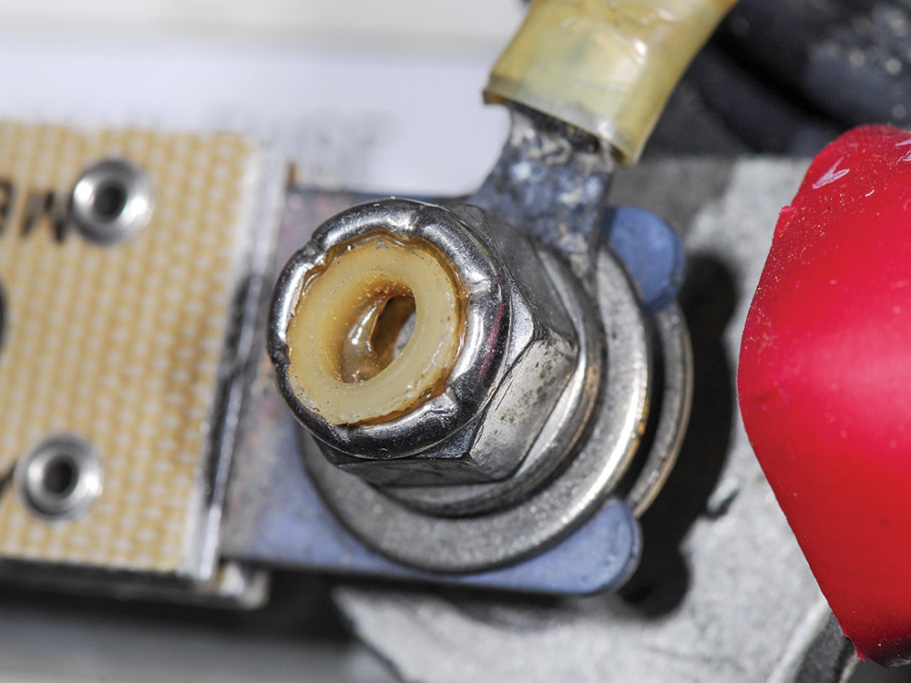
In order to ensure minimal resistance, ring terminals must be installed from largest to smallest, so the greatest amount of current is passing through the largest ring terminal. This error is especially common on starter posts, so check yours carefully. Yet another ring-terminal faux pas involves the installation of a washer, nut or other component between the ring terminal and the component to which it’s being connected (such as a bus bar, battery terminal or fuse block). In most cases, it’s a stainless-steel washer that is installed by a well-meaning individual who believes he or she is diminishing the likelihood of corrosion. In fact, this practice increases the likelihood of overheating and fire. Stainless steel, when compared to copper, is a poor conductor. Using it to convey high current (for example, with a windlass or starter) is like forcing water from a garden hose through a small funnel; the resistance is high, and when it comes to electricity, high resistance equals heat. Nothing should come between ring terminals and the object they are conducting electricity to or from. Period.
Finally, high resistance remains an ever-present threat where shore power is concerned. Statistically, shore power plug connections are among the leading causes of fire aboard boats. Get into the habit of inspecting both ends of the shore cord as well as the receptacles aboard the boat and ashore. If any appear to be overheated, melted or burned in any way, they should not be used. This is a problem that is largely prevented by making sure certain plugs and receptacles are clean and dry. If a molded cord end is dropped into the water, it should be thoroughly washed with fresh water, dried and sprayed with corrosion inhibitor that’s suitable for electrical connections. If it’s an assembled rather than a molded plug, it should be disassembled and cleaned before it’s used.
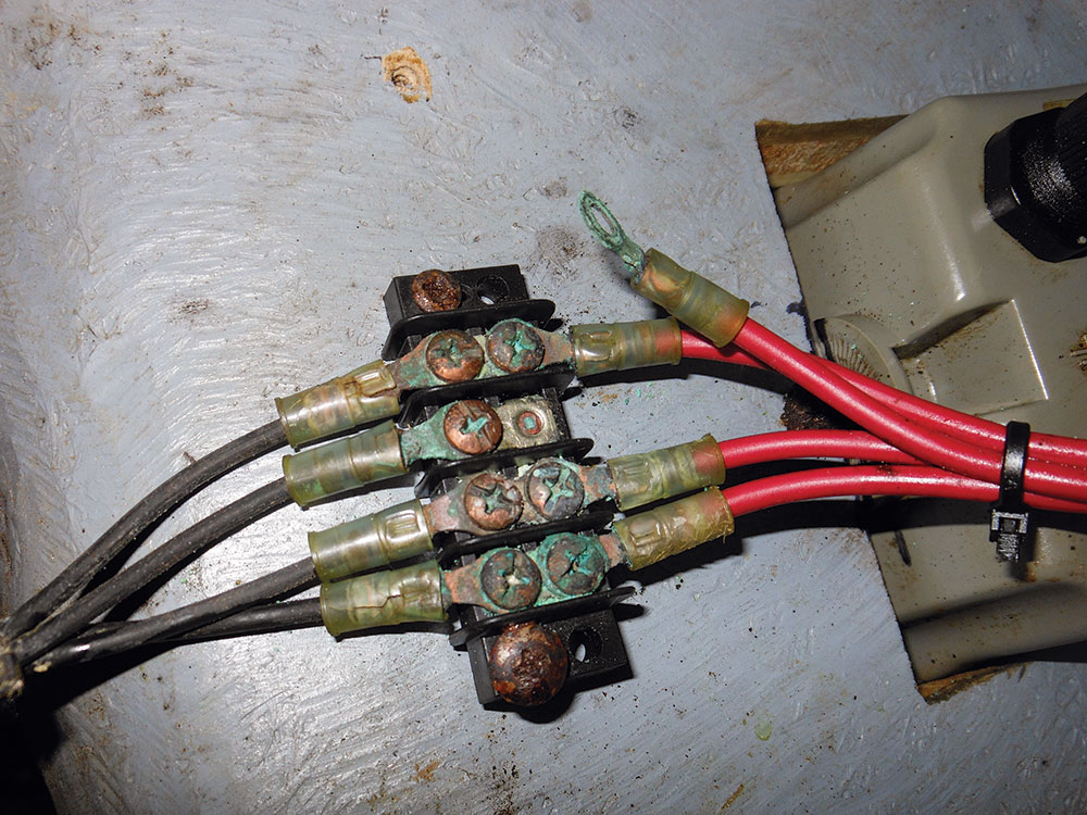
Corrosion One statistic holds that the global cost of corrosion is more than 3 percent of the planet’s GDP. For boats, clearly, it’s far greater. But much of this is preventable, particularly where your electrical system is concerned.
The selection of corrosion inhibitors is almost as dizzying as fuel additives. For the most part, they fall into two categories: light films that also include some lubricating properties, and heavy coatings that dry to a waxlike consistency. For components that are routinely removed and replaced, such as shore power cords and other plugs, light films are appropriate. For connections that are semipermanent, such as battery terminals, bus bars, ring terminals and so on, the heavier waxlike products make more sense.
For ring terminals, batteries, bonding systems and other screwed-in-place electrical connections — especially those located in damp areas such as bilges or sail and chain lockers — use the following approach: Make certain the power is off, then disassemble the connection. If there’s any corrosion or patina, clean it using a 3M Scotch-Brite pad. Then clean it again using a dedicated electrical contact cleaner such as CRC QD. Finally, apply either a conductive paste or dielectric grease to the contact area (either will work well, though I prefer a conductive paste with the aforementioned caveat regarding closely spaced positive and negative contacts); reassemble; torque; and then spray with the heavy waxlike corrosion inhibitor, my preference being the CRC Heavy Duty Corrosion Inhibitor.
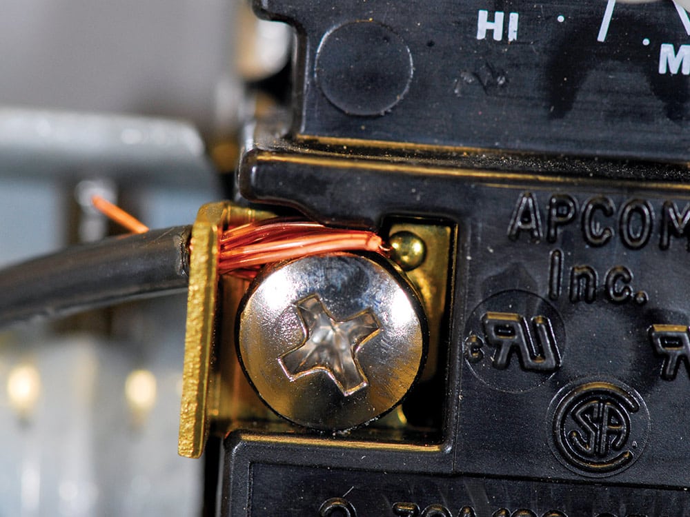
Beyond this sort of prevention, there are a few other tricks that can be used to keep electrical corrosion at bay (female ends should be blown out with compressed air if possible). Every attempt should be made to install bus bars and other electrical components on vertical rather than horizontal surfaces. Doing so makes it less likely they will be dripped on or stand in water. Drip shields can easily be fashioned using Plexiglas (battery chargers and inverters, if not already drip-proof, should be installed with drip shields), or components can be installed in plastic electrical enclosures. When using the latter approach, wires should always enter from the bottom of the box. If they must enter from the side, include a drip loop to prevent water from using the wire as a leader into the connection area. While electricity and seawater don’t typically mix, a truce can be struck between the two, provided a proactive approach is taken.
Longtime boatyard operator Steve D’Antonio offers services for boat owners and buyers through Steve D’Antonio Marine Consulting.

