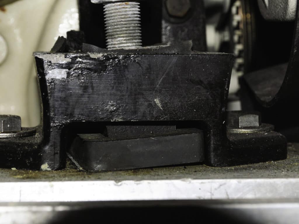
It comes as a surprise to many boat owners that the only thing transmitting thrust from the propeller to the vessel’s hull, moving the hull forward, is the motor mounts. And, that the only connections between the prop and the hull are four ½-inch or 5⁄8-inch studs. A great deal of faith must be placed in those studs, so it’s worth making sure they are properly installed and maintained.
And not just because they transmit thrust. A motor mount also absorbs vibration and torque, using a rubber or synthetic material as the medium. It’s difficult, if not impossible, to design and construct a motor mount that does all three tasks equally well.
Absorbing vibration requires a softer durometer, while transmitting thrust and contending with torque requires a more robust durometer. The engine wants to counter-rotate in the opposite direction from the prop, which means the mounts on one side of the engine are compressed more than those on the other side. In some cases, the mounts on one side might actually be lifted, which means they are in tension rather than compression. For this reason, some engine manufacturers specify different durometer mounts for left and right.
Taking these variables into account, most mount designs must represent a compromise across the range of use.

Commonly, the cause of motor-mount failure is related to installation and the length of exposed stud. Ideally, motor mounts should not be adjusted to the limit of their travel, up or down. Motor mounts are the primary mechanism for adjusting engine location relative to the propeller shaft, otherwise known as alignment. The coarse adjustment should be performed by the boatbuilder or engine installer using shims, or by removing some of the stringer to depress the mount.
The goal is to get the engine bracket, which connects the engine to the mount stud, somewhere in the middle of the coarse-adjustment range. Then fine adjustment takes place, with the engine being moved a small distance up or down. If the engine is at the top of the stud’s adjustment at the end of this process, the leverage imparted to the stud can lead to its failure. If the engine is at the bottom of the stud’s travel, no further adjustment is possible—a potential problem for future alignment.
Fasteners used to secure the mount’s base to the stringer or shelf on which it rests should be a through bolt, machine screw or lag bolt, in that order. Through bolts offer the greatest security. Machine screws that are screwed into a tapped metal plate embedded into the stringer are a close second, although if they strip, repair can be difficult. Lag bolts are less than ideal because their coarse threads are engaging fiberglass and likely timber, which can fracture or strip if overtightened. And, if the timber gets wet, it will rot, allowing the fastener to pull out.
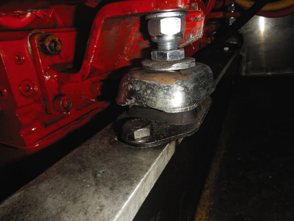
The fasteners should be the same diameter as the hole in the mount base. There should be no slop or play. If there is, the engine might shift fore and aft when changing gears. Because of the cyclical and reversing nature of loads on mounts, fasteners are prone to loosening. Nylon insert locking nuts or cam-style lock washers should be used to ensure their security. Mounts should be aligned parallel to the vessel’s centerline, and studs should be perpendicular to their base. If twisted, the life of the flexible inserts can be severely shortened.
Motor mounts should be inspected regularly. The studs and the shell (or cap) are usually mild steel, so they should be corrosion-inhibited. Check all adjustment and mounting hardware, making certain it is tight; you’ll need to put your fingers on each one to do this. If you see any indication that the mount base is sliding, that’s cause for concern.
Finally, look for signs of deteriorating flexible insert material, which will often show up as black dust or “crumbs” around the base of the mount.
Steve D’Antonio offers services for boat owners and buyers through Steve D’Antonio Marine.

