MultimeterAmps
In the third of this ongoing series on digital multimeters, we’ll address ampere measurement. Electrically speaking, amps do the heavy lifting. Sufficient amperage enables starter motors to overcome the compression and resistance of an engine’s pistons for cranking purposes. Amps allow a high-output alternator to recharge a large battery bank relatively quickly. The ability to measure amps with a multimeter is invaluable for identifying or isolating a variety of problems, from a malfunctioning voltage regulator to a defective or shorted battery.
Amps aren’t measured the way that voltage is, a critical difference. Last month, we discussed how voltage is measured in parallel; for instance, when a multimeter’s positive and negative test leads are placed on the positive and negative terminals of a battery. Conversely, amperage is measured in series. When any electrical component is placed in series—be it a multimeter, a light, or a battery—it’s essentially inserted into a circuit rather than alongside it or in parallel. For measurement purposes, this means that up to about 10 amps, the multimeter becomes part of the circuit as a current-carrying conductor. For example, if you wanted to determine how much current an anchor light used, you’d separate one of the light’s conductors at the base of the mast or the electrical panel. Setting your meter to AMPS DC, you’d then attach one lead (it doesn’t matter which) to the wire leading to the light and the other to the energized conductor that ultimately travels to the source of power, the battery. (These two conductors are referred to respectively as the “load” and the “line.”) When power is applied, the light is illuminated, and the meter will simultaneously indicate how many amps are being drawn. A 12-volt, 20-watt light should draw about 1.5 amps. If, however, it’s drawing 8 amps, you might conclude that the insulation on the positive wire leading up the mast conduit (all mast wiring should be in a conduit) has chafed and is creating a “pseudo” short circuit. This will unnecessarily consume battery power, and it may also accelerate mast corrosion.
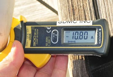
Most multimeters will safely carry up to 10 amps for measurements of this sort. Beyond that, however, their internal fuse should blow to prevent damage to its circuitry. For obvious reasons, try to avoid testing that function. If you want to measure the amount of current (another name for amperage) produced by the alternator or consumed by the starter, buy an amp meter that includes an inductive “amp clamp.” These scissors-like jaws can be spread and placed around a conductor, enabling you to measure hundreds of amps safely and easily without ever touching or disconnecting a wire. I rely upon this useful tool regularly for troubleshooting.
There’s one caveat to using an inductive amp clamp: If you wish to measure current, the clamp must be placed around a single wire only. If you place it around several wires within a cable, such as an AC extension cord, the hot and neutral conductors within the cable will neutralize the inductive field, and the meter will read zero. If you place your inductive amp clamp around your shore-power cable, for instance, it should read zero. If it doesn’t, that may indicate a serious and potentially dangerous fault that’s allowing the water in which your boat floats to act as a return path for electricity. Should that be the case, unplug your boat from the dock and call an American Boat & Yacht Council-certified marine electrician to check the system for faults.
Steve D’Antonio offers services for boat owners and buyers through Steve D’Antonio Marine Consulting (www.stevedmarineconsulting.com).


