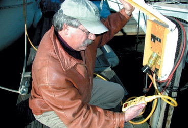
Ed Sherman testing
This one’s for Lucas.
On August 1, 1999, 9-year-old Lucas Ritz jumped into the water off his family’s boat at Casselman’s Cove Marina in Portland, Oregon, to play with friends. Lucas was wearing a life jacket, and his mother kept a close eye on him. When he’d had enough swimming, Lucas approached the dock. As he was lifting himself out of the water, witnesses said they heard him let out a loud gasp and saw him roll over onto his back, apparently unconscious. His Type-II PFD kept his face out of the water, as it was designed to do. Sheryl Ritz, his mother, yelled to the other kids to help him, and she jumped into the water. As the kids approached Lucas, they said they felt a tingling sensation and backed away. Sheryl’s extremities went numb, and she had difficulty moving. She did manage to get Lucas to the dock, and with the help of others got Lucas and herself out of the water. At this point, Kevin Ritz, Lucas’ father, came to the scene. They administered CPR until the paramedics arrived 15 minutes later. At 6:30 that evening, Lucas was pronounced dead.
He’d been electrocuted.
What caused this tragedy? Lucas’ death was quite conclusively attributed to faulty boat wiring and inattention to one of the most important electrical systems on any boat, the grounding system.
One System, Many Roles
A boat’s grounding system may serve any of five roles, depending on how your boat is equipped.
• Its primary purpose is to minimize the risk of electrical-shock hazards to people on board the boat in the event of a short-circuit fault in an appliance supplied with alternating current (AC).
• Some components, such as battery chargers and inverters, carry high-amperage direct current (DC). These need DC grounding to ensure that any short circuits return to their sources and trip a circuit breaker rather than ignite an electrical fire.
• A grounding system should connect all onboard metal objects, including metal-cased electrical devices, tanks, through-hull fittings, rudderstocks, and engines. This does two things: It minimizes the risk of stray-current corrosion, and it protects against sparks from static electricity that could ignite onboard fuels.
• This same system may be tied to a subsystem for lightning protection.
• Boats with single-sideband or ham radios need a grounding system to provide antenna counterpoise and minimize radio-frequency interference (RFI).
Of all these roles, it’s mainly the first one—shock-hazard protection for boats with AC equipment installed—that interests us here. But the others will play a part, too.
A normal AC circuit carries three conductors: a hot (black) conductor, a neutral (white) conductor, and a grounding (green) conductor. The neutral conductor is tied to a ground plate at the AC power source—which could be a genset, an inverter, or a shore-power box. Electrically, the neutral conductor maintains ground potential. The hot conductor delivers voltage that alternates in relation to ground potential. It’s this voltage difference that powers the appliance. With just these two wires, the circuit is complete.
The main purpose for the third wire, the grounding (green) conductor, is to protect against shock hazards. When the system’s operating normally, the green wire shouldn’t carry any current at all. To understand its role, we need to explore what happens in the event of a “ground fault,” a situation that occurs when current finds an alternative path from the power source to ground. Ground faults can occur in high-level or low-level degrees.
A typical high-level ground fault is called a short circuit to ground. In that scenario, through corrosion, loose connections, or poor insulation around the conductor, current is delivered to the metallic case of an appliance. Without an alternate route for the fault current to travel back to the source of power, the case of the equipment becomes live. If a person touches the case, his body becomes the alternate route to ground, bypassing the neutral (white) conductor and exposing him to full AC voltage potential—likely a lethal encounter. Here’s where the grounding wire comes in. This third wire, attached to the case of the appliance, carries the fault current back to the power source and trips the circuit breaker, shutting off current flow. Marine-grade circuit breakers are designed to be “trip-free,” which means the circuit can’t be turned back on until the problem is solved.
All of this raises an essential point regarding the grounding system in AC circuitry. The green wire must take a direct path back to the source of power and at that point be connected to the neutral conductor for the scenario above to play itself out. This gets a bit confusing on boats with multiple AC power supplies (say, for instance, a genset, an inverter, and shore power) when it comes to switching from one source to another. The system must be configured so that both the hot (black) wire and the neutral (white) wire get switched from one source to the next, but the green wire doesn’t. The grounding connection must always be continuous to the ground point at the power source.
Considering the system design so far, it would seem that all is well, regardless of what happens in terms of an AC short circuit. But, unfortunately, that’s not quite true.
Current Splitting
We said earlier that there can be high-level and low-level ground faults.
The above example works because the short circuit delivers high amperage back to the source through the green wire and trips the circuit breaker. That scenario doesn’t address two other circumstances: a low-level AC fault within an appliance, and a short circuit from AC wiring to nearby DC wiring when those conductors aren’t properly sheathed and supported. It was the latter situation that caused Lucas’ death.
The American Boat & Yacht Council (ABYC) and other international bodies provide standards for sheathing and supporting wire runs. As an AC appliance ages, the insulation of its inside components can break down gradually, allowing some leakage of fault current to the case. Yes, the green grounding wire will carry this fault current back to the source. But the actual leakage current might be only 3 amps for a circuit that normally carries, say, 12 amps. Assuming the system was originally engineered correctly, the circuit breaker—which should be sized to carry the maximum load the conductor can safely handle before opening—won’t trip. A breaker’s job is to protect a circuit from excessive current, and in this case, the wiring can certainly handle the current. This means that a low-level leakage current can migrate around the grounding system for an indefinite amount of time without piquing anyone’s attention. Therein lies the fatal flaw.
There’s a popular misconception that any AC fault current will travel the shortest route back to its source via the green grounding wire. But the evidence doesn’t always support that notion. Remember when we spoke earlier about the five roles a boat’s grounding system plays? This is where some of the others come in. Depending upon actual resistance values within the system, some of the leakage current may actually end up being delivered via the grounding system that ties seacocks and through-hull fittings to the seawater your boat floats in. To minimize this tendency of fault current to find an alternate path, it’s absolutely critical to maintain the AC grounding system, keeping connections tight and free of corrosion.
Truth is, in a seemingly perfect system, fault current will be split between the shore-power system on your boat and the water the boat floats in. No matter what, it’s seeking a path back to Mother Earth. Depending on the resistance of the water itself, the current may actually ride on or near the surface back to the beach (typical in fresh water, which is more resistant than salt water), or it may seek the earth directly under your boat (typical in more-conductive salt water). Casselman’s Cove Marina is in fresh water, and this could account for the tingling sensation that Lucas’ friends felt and, in the more extreme case, the actual numbing effect that Sheryl Ritz experienced.
Unfortunately, there’s no standard in the United States or Europe that requires monitoring of ground-system fault current on boats. I increasingly feel that this is a matter that needs to be revisited by the standards-making groups for boats equipped with AC electrical systems. The mere addition of GFCI receptacles (ground-fault circuit interrupters with a 5-milliamp trip rate) near such wet locations as heads and galleys isn’t enough to ensure that the entire AC system is protected against low-level ground faults. Such devices as water heaters, air-conditioners, and refrigeration systems are typically not connected to these devices on American-built boats that are completely compliant with ABYC electrical standards.
European boats are different. They’re typically fitted with a 30-milliamp trip device at the AC main panel, which provides “whole boat” protection. In my view, this is a safer approach. This 30-milliamp value is probably a fair compromise on a small boat with few AC systems on board. The issue here is that some experts fear nuisance tripping, with frustrated owners simply bypassing the breaker rather than fixing the faulty device; this is why the Americans have never embraced this concept. But I consider this a lame argument. This level of protection almost surely would have saved Lucas’ life.
Isolating Fault Current
The AC portion of a boat’s grounding system needs to be connected to the DC section of the system. This must be done at exactly one location in the system, according to the ABYC: at the “engine negative terminal or its bus.” This vital connection is to ensure a ground-fault path back to the source in the event of a short circuit inside a device such as a battery charger or inverter that has both DC and AC circuitry contained within its case. Experience has shown us those short circuits that migrate from the DC to the AC side or vice versa aren’t at all uncommon.
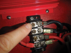
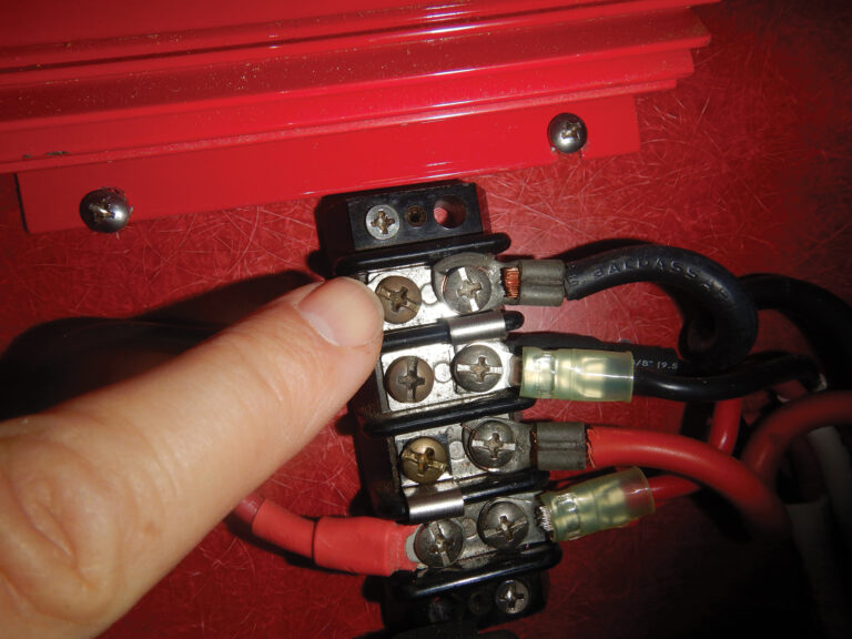
Battery chargers and inverters are also required to have a DC grounding conductor attached to the metallic case with the capability to handle amperage for a full-on DC short circuit to the case. The problem here is that the AC case ground wire will invariably be much smaller than the wires needed to distribute the DC fault current. This is due to the difference in voltage potentials between the AC and the DC sides of the device, a difference that’s typically tenfold. Ohm’s Law (voltage = amperage X resistance) describes the inverse relationship between voltage and amperage. Because wiring is sized to handle a given amperage, it follows that the wiring for a 120-volt AC circuit will be much smaller than that for a 12-volt DC circuit. So, while this DC grounding wire may seem redundant, it is vital. Standards dictate that it be no smaller than one wire gauge size under those used for the normal DC circuitry to and from the charger or inverter. Without it, the AC grounding wire would likely burn through and ignite a fire on board in the event of a DC short circuit to the case. We’ve seen that happen plenty of times in the field.
This important link between the AC and DC grounding systems has often been a contentious point among technicians, and some say it’s the root cause of AC leaks out of a boat via its through-hull fittings. Actually, there’s some truth to that, as we discussed above in the section on current splitting.
Historically, experts in marine electrical safety have concerned themselves primarily with protecting people aboard the boat from the dangers of ground faults. Some leakage of fault current to ground outside the boat was tacitly deemed permissible, a reasonable exchange for keeping people safe on board. Fair enough. In a saltwater environment, statistics have shown that this fault current is quickly dissipated. We simply have no data suggesting that the events that led to Lucas Ritz’s death pose a serious risk in salt water. Still, it’s not at all uncommon to hear of divers who perform underwater service to boats in salt water reporting that they’ve felt that unnerving tingle when actually touching the emitters of this underwater fault current. But in those cases, the current densities involved are insufficient to cause much more than a tingle.
The facts show us that properly maintained and designed grounding systems have saved many, many lives—far more than they’ve placed at risk. But there’s another point that can’t be overlooked. A perfectly designed and ABYC-compliant boat with a well-maintained grounding system is only as good as the dock ground it’s connected to. And there’s the rub. The incidence of failed or inadequate grounding conductors on docks is high.
How can you know if your marina’s grounding system is adequate? Merely measuring electrical “continuity” of a grounding conductor isn’t enough to ensure that it can carry a lethal fault current. In marine applications, we use multistrand wire conductors. Strand count affects a wire’s current-carrying capability. You can have two strands connecting two points in a circuit and get a good continuity reading no matter how you test it. The question is whether it can carry fault-level current when called to duty. The answer is no. The two strands would surely burn through.
I know of one tool that can diagnose dock wiring—the SureTest Circuit Analyzer (Ideal Industries). By using this device regularly on your dock, you can determine if the grounding conductor’s resistance value has changed or reached a potentially dangerous point. The National Electrical Code defines “grounded effectively” as a “ground connection having sufficiently low impedance (resistance) and having sufficient current-carrying capacity to prevent the buildup of voltage that may result in undue hazards to equipment or persons.” In the real world, you’ll see readings all over the chart, anywhere from less than 0.25 ohms to nearly 1.0 ohm. To be safe, I always embrace the 0.25 ohm end of the spectrum. The Sure-Test works by sending a 15-amp current down the green wire for just enough time for its microprocessor to measure the electrical resistance in the wire. The meter also measures such other values as line voltage and voltage drop (excessive voltage drop indicates undersized or damaged power-feed wiring). It also performs a comprehensive test of onboard GFCI receptacles and checks for reversed polarity. You’ll need to either buy or make an adapter to convert the tool’s 15-amp plug into a regular 30-amp shore-power receptacle.
The grounding system on most boats is arguably the most ignored and neglected part of any electrical system. After all, it really doesn’t make anything work better on your boat; it’s nothing more than a backup system. But I hope that after reading this, you’ll take the time necessary to check this vital system on your own boat. Ask questions about your marina’s policy on inspecting dock wiring. To satisfy yourself that your dock is safe, periodically perform the checks outlined here. Perhaps you’ll also understand why many marinas now post No Swimming signs. If only more people had known about the proper isolations of fault currents back in 1999, Lucas Ritz would still be alive.
Ed Sherman is the curriculum designer for educational programming, the manager of instructional personnel, and the senior staff writer for the American Boat & Yacht Council (www.abycinc.org).


